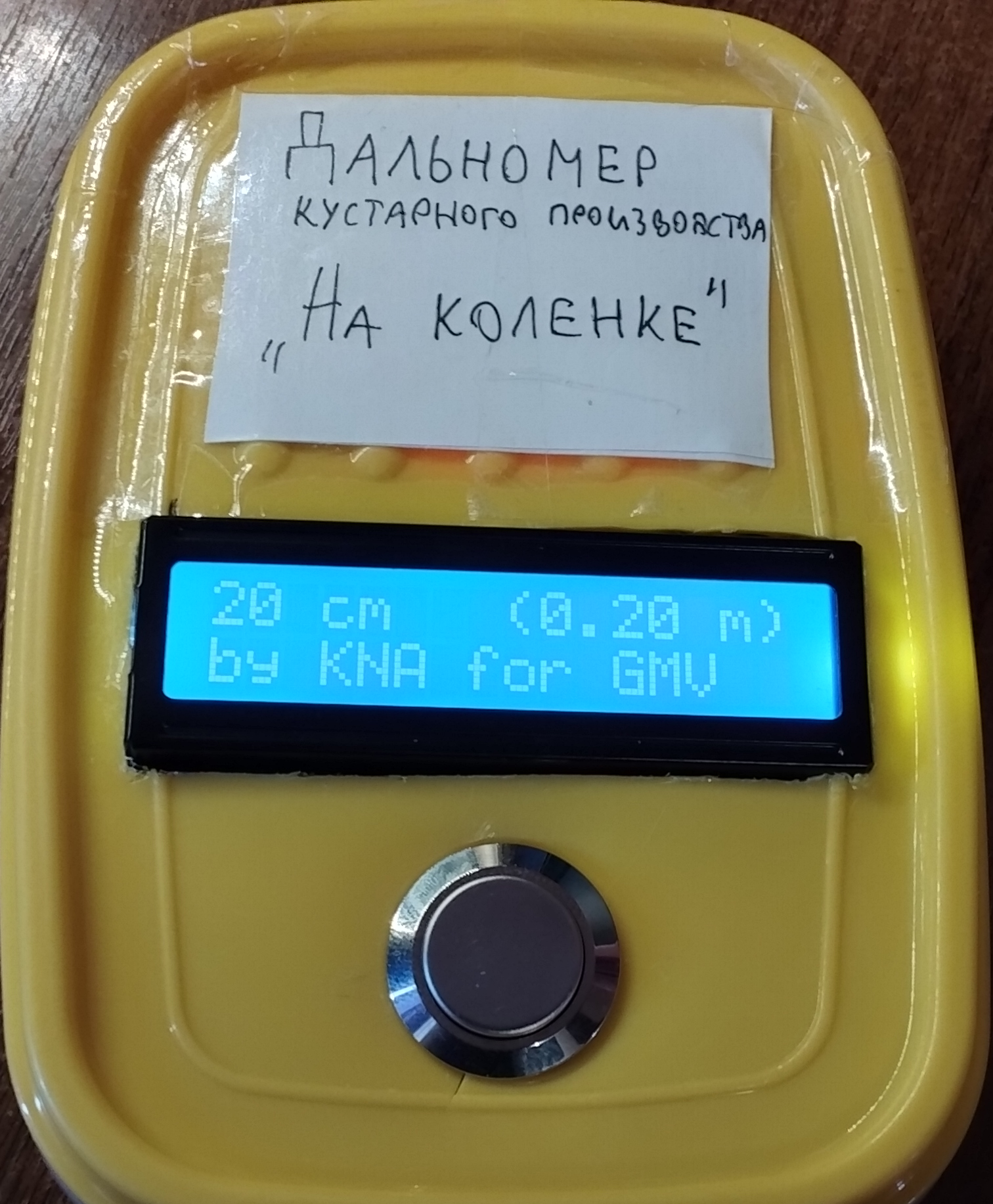
A really bad rangefinder
Foreword
Before I've started programming, in my early teens (13-15) I was really passionate about electronics but due to my back then limited knowledge a lot of junk I've had bought off Aliexpress was lying on top of my desk for almost like what, 3-4 years without any use, only a small portion was lucky enough to go into actual mere underprojects. So as a tl;dr: I had a lot of junk and I wanted to do something even remotely practical with it.
Whilst the process of making is unprofessional, the outcome is neither a candy to the eye nor seriously useful, I've extracted a lot of experience from it and that's the sole purpose of the this half-baked memebox.
If you have hands growing from the right places unlike me - you'd get a lot better results.
High level overview
Arduino waits for a button to be clicked upon which tells the controller to start the display, at the same time it endlessly fires up ultrasonic sensor, which sends time the waves spent going to the obstacle and back to the arduino, then the controller calculates distance and finally transmits a ready-to-display message to the screen.
Source components
| Component | Picture |
|---|---|
| Arduino UNO |
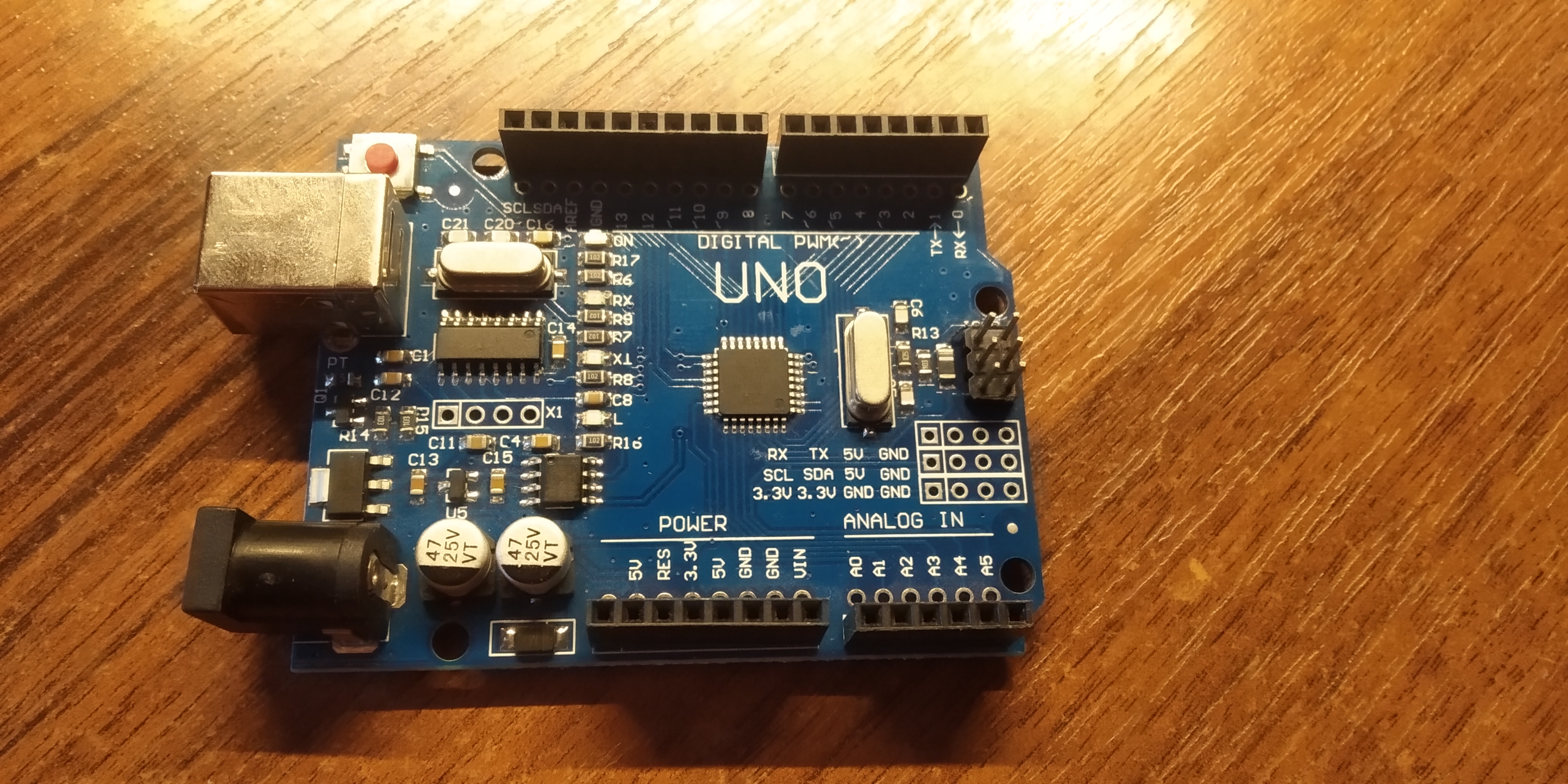
|
| Some random rechargeable Chinese "Крона" battery |
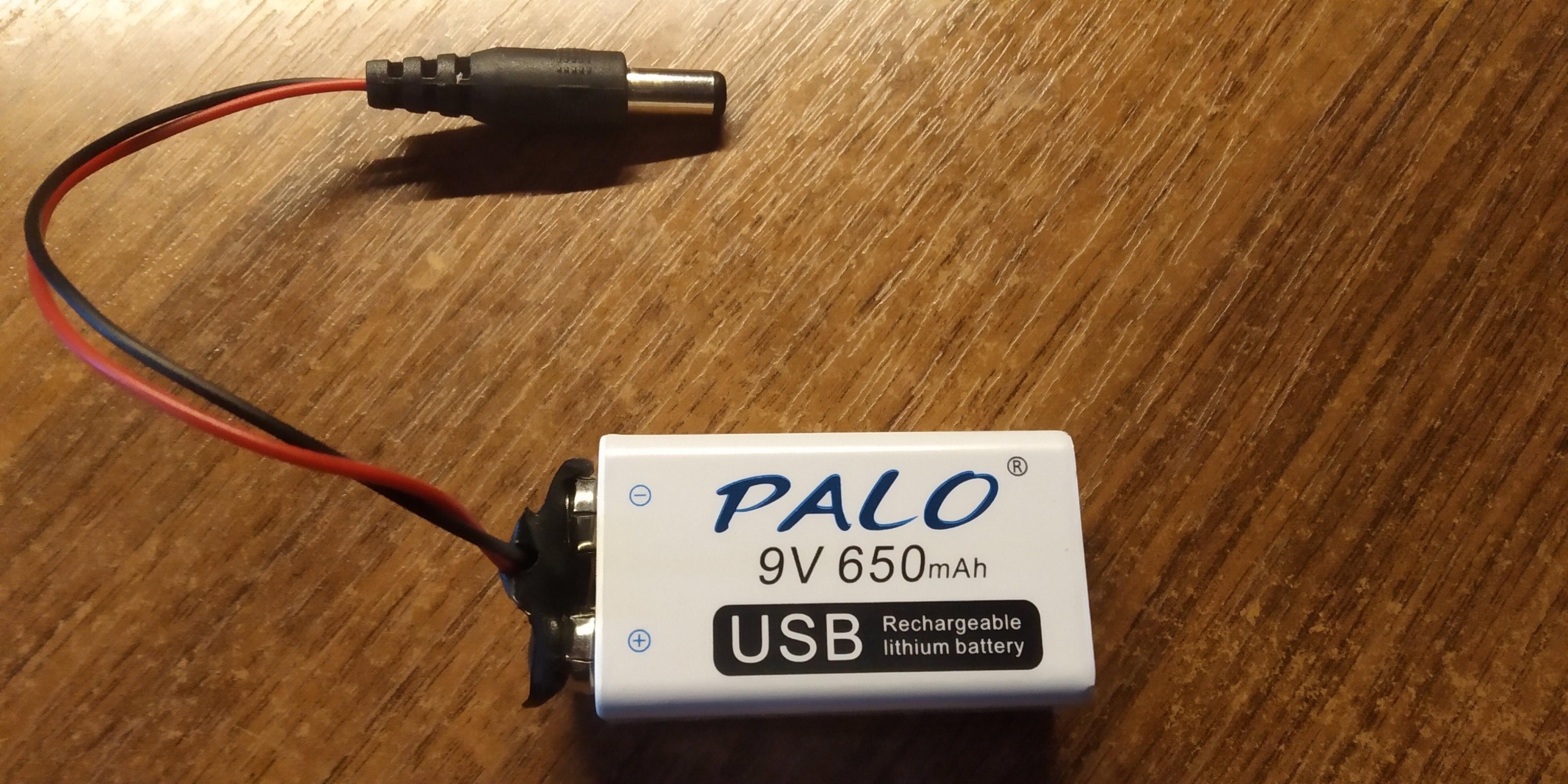
|
| Not less random Chinese button |
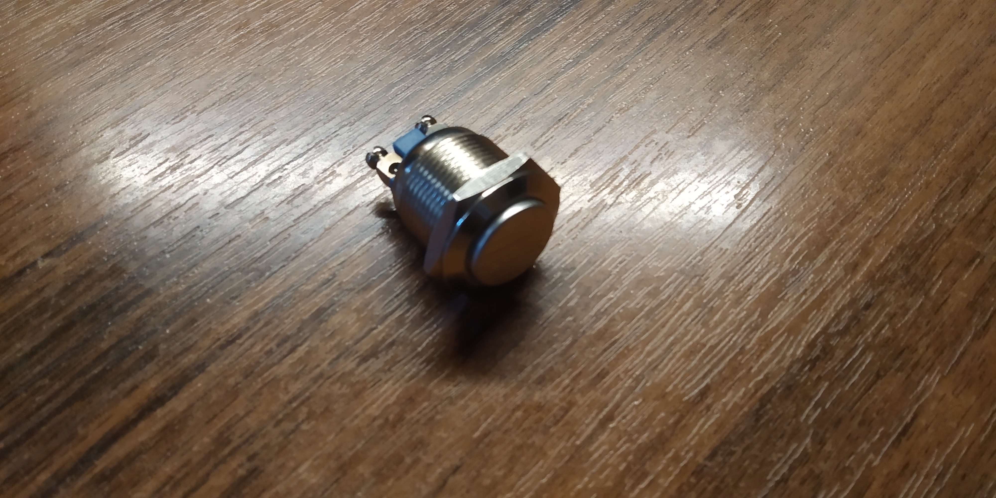
|
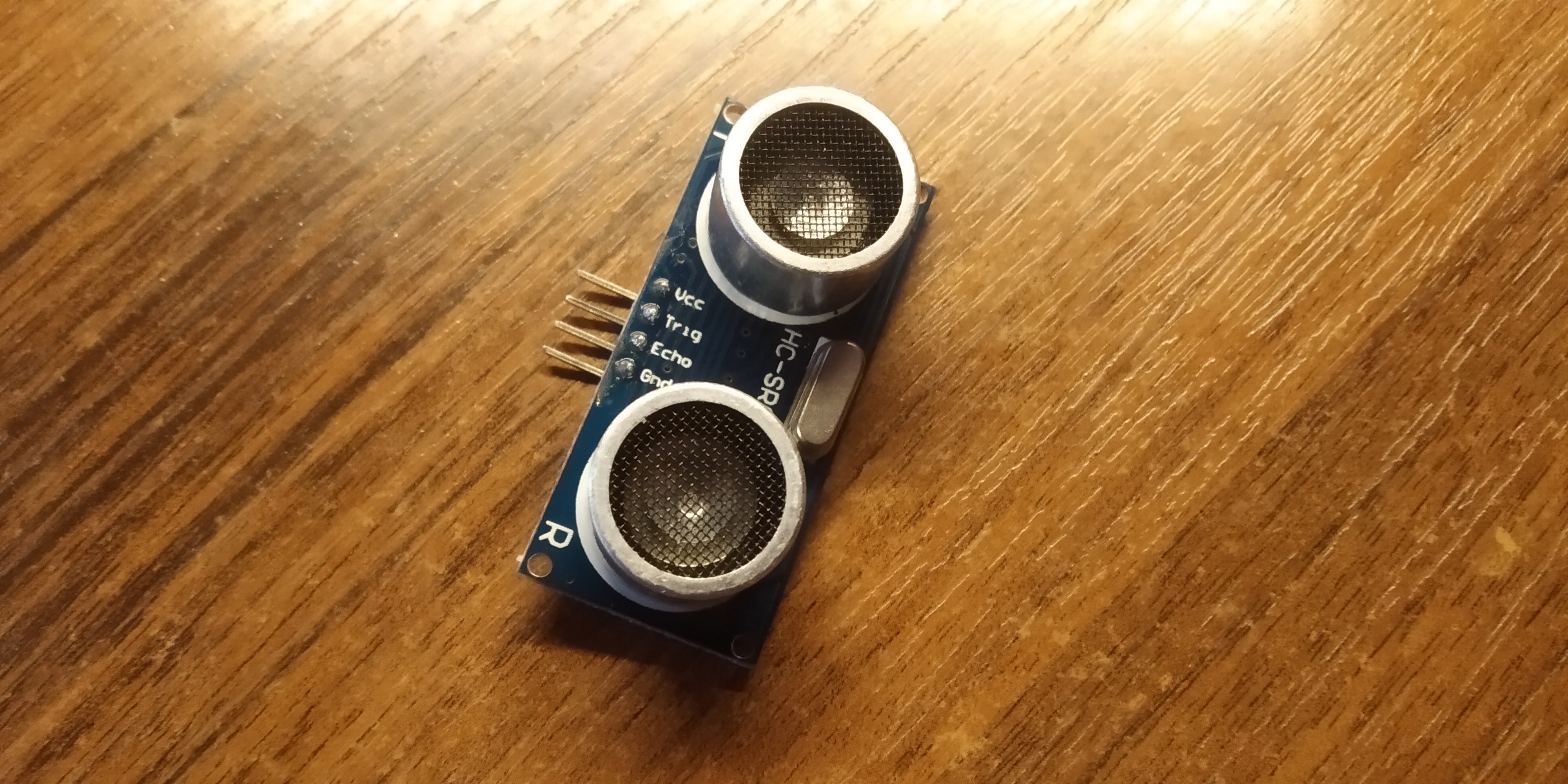
| HC-SR04 ultrasonic sensor |
|
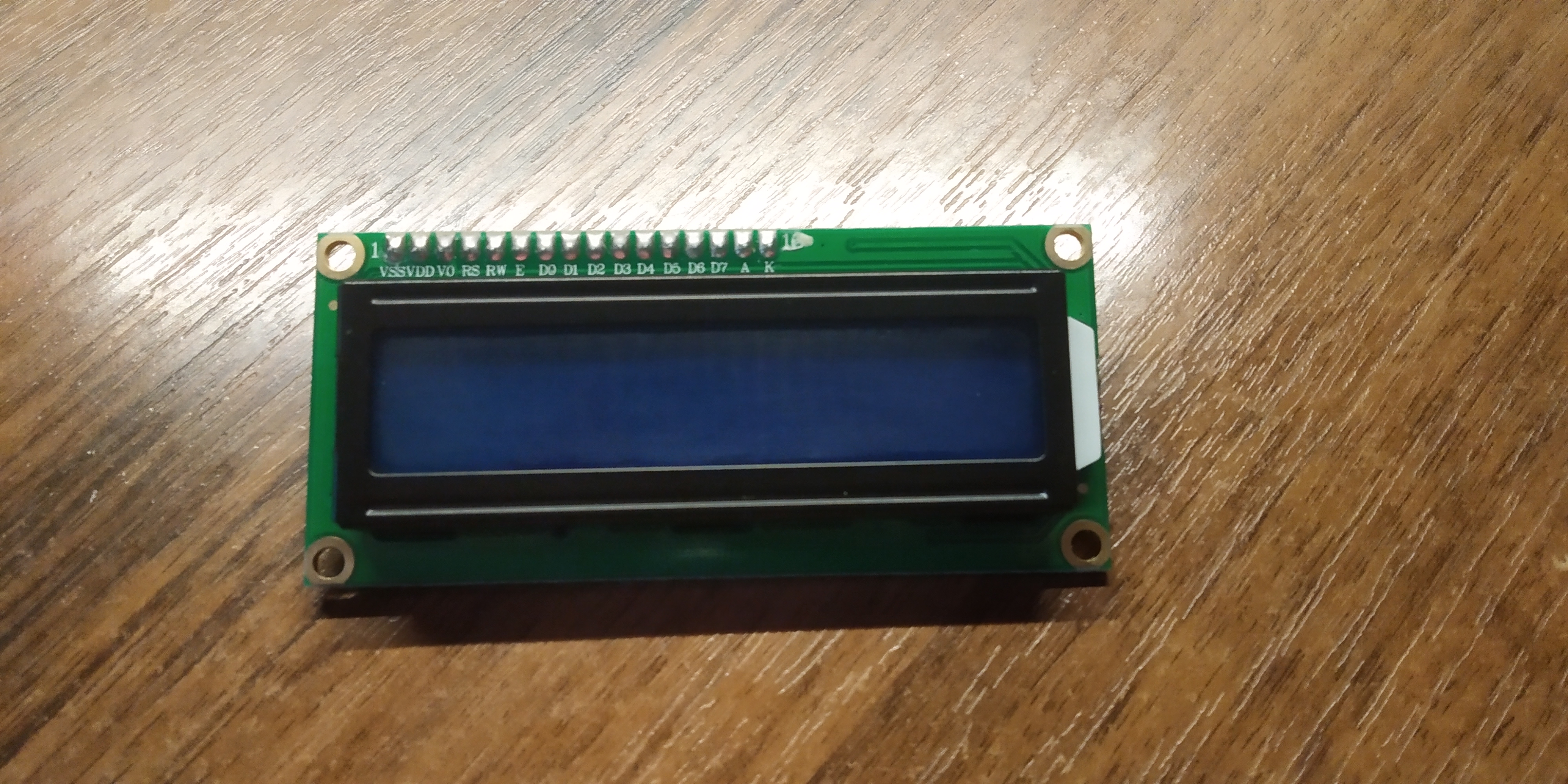
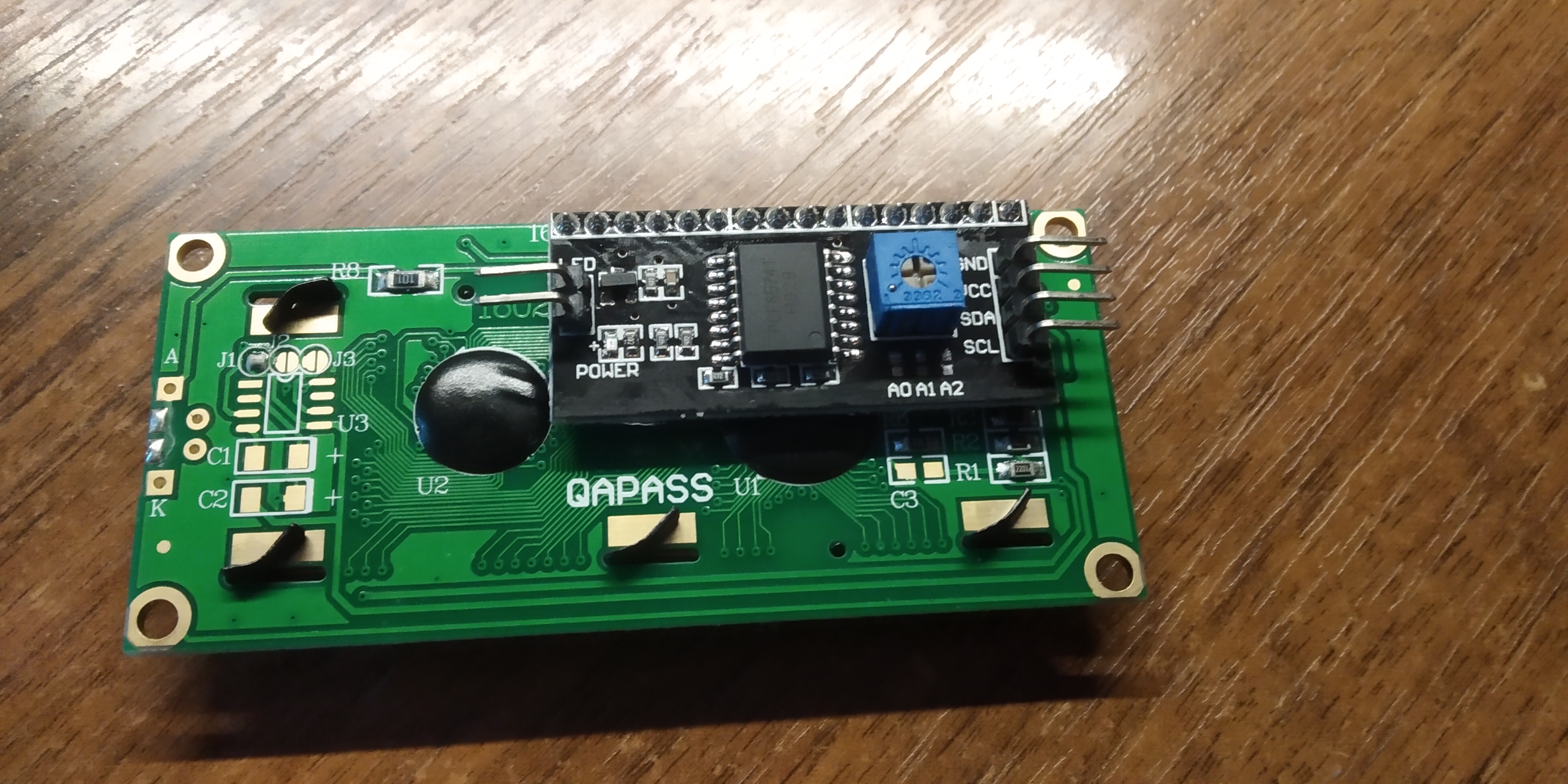
| LCD 16x2 character display with a driver |
|
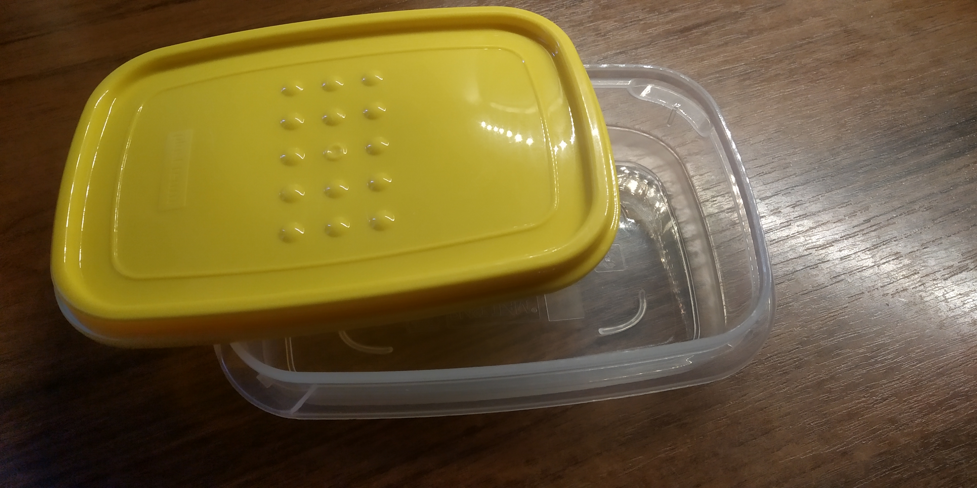
| The B O X |
|
And a lot of wires.
If I had the ability to change the components, that would definitely be the sensor. This boy is not reliable, it frequently gives unexpected and unstable results: one second pointing at one place - it shows (for expample) 40cm, the other second at the same place - it's 80cm on the display. The reason might be the waves, which are not spreading in a straight line; if the sensor is used in an "obstacle populated" area - there is a big chance you'd get the time wave traveled to the nearest entity (and therefore the wrong distance) but not at something you'd pointed the sensor at. The optical sensor would be a more reliable replacement I guess.
Wiring
Basic schematics without the box as a frame.
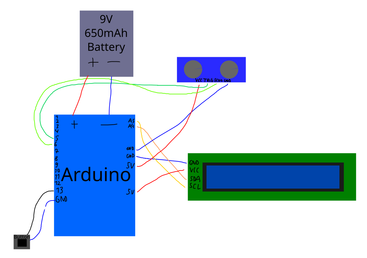
Horrible, not school-approved, but at least something.
| Component | Pins |
|---|---|
| Button | GND and pin 13 |
| Sensor |
VCC - V5 Trig - pin 5 Echo - pin 6 GND - GND |
| Display |
GND - GND VCC - V5 SDA - pin a4 SCL - pin a5 |